

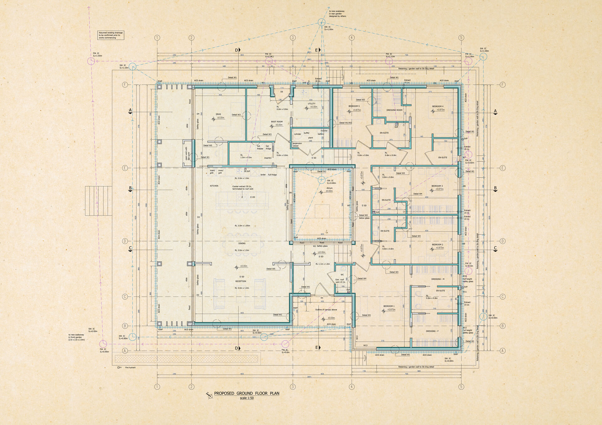
Construction Drawings: Where Good Design Becomes Clear Instruction
There is sometimes a slightly blurred distinction in residential construction between planning drawings, Building Regulations drawings and what might more accurately be described as a construction or technical package. Depending on who you speak to, these drawings might be called Building Regulations drawings, construction drawings, technical drawings or a Stage 4 package. The terminology varies, but the underlying purpose should be relatively straightforward: once we know what we have permission to build, somebody needs to explain how we are actually going to build it.
Under the RIBA Plan of Work, this detailed development of the design principally sits within Stage 4, Technical Design, before moving into Stage 5, Manufacturing and Construction. On smaller residential projects, the boundaries can naturally become less formal, particularly where the architectural designer, structural engineer, contractor, Building Control body and other specialists are contributing information at different stages.
Whatever terminology is used, I think there is an important distinction to make. A good construction package should not exist solely to obtain Building Regulations approval. It should communicate the proposed building to the people who are actually going to construct it.
That sounds obvious, but the two objectives are not necessarily the same.
A drawing might contain enough notes and specifications to demonstrate that the designer has considered the relevant requirements of the Building Regulations, but that does not automatically make it an effective construction drawing. If a contractor cannot easily establish what is being built, where it is being built, how the different components relate to one another and where to find the relevant detailed information, then the package has arguably failed in one of its most important functions.
For me, the quality of a technical package therefore comes down to communication, coordination and the removal of unnecessary uncertainty before it reaches the building site.
Building Regulations are only part of the story
The Building Regulations in England cover an enormous range of technical requirements. Structure is principally addressed through Part A, fire safety through Part B, moisture and contaminants through Part C, ventilation through Part F, drainage through Part H, protection from falling and impact through Part K, conservation of fuel and power through Part L and electrical safety in dwellings through Part P, alongside numerous other requirements depending on the nature of the project.
These requirements are obviously extremely important. A building needs to be structurally safe, people need appropriate means of escape from fire, stairs and guarding need to be safe, ventilation needs to be adequate, drainage needs to function and the thermal envelope needs to achieve the required performance.
However, Building Regulations compliance is not the same thing as construction information.
A note on a drawing might establish the required U-value of a wall, for example, but somebody still needs to explain how that wall is constructed. What blockwork is proposed? What insulation is being used? How thick is it? What performance does it need to achieve? How does the insulation continue around openings and junctions? How does the wall meet the floor and roof? What happens at the cavity closer, lintel and damp-proof course?
That is where technical design becomes construction communication.
Start at the beginning of the build
When we prepare a construction package, we generally try to organise the information in a similar sequence to the way somebody might begin thinking about constructing the project.
We start with the existing building. Even though the contractor can obviously see the property on site, existing drawings provide an important reference against which the proposed work can be understood. Depending on the complexity of the project, we may also produce a demolition drawing clearly identifying which walls, structures, fixtures or other elements are to be removed.
That information has practical value before construction even begins. A contractor can start to understand the extent of demolition, temporary works that might be required, waste removal, skips, labour and sequencing. It can also clarify which parts of the existing structure need to remain in place until later in the construction programme. On some extensions, for example, it may be preferable to construct much of the new envelope before breaking through into the existing house.
We then move onto what I consider one of the most important drawings in the entire package: the foundation and drainage plan.
Understand what is underneath the building before you start
A surprising number of expensive construction problems originate underground.
Before foundations are excavated, we want to understand the existing drainage arrangement as well as reasonably possible. Where necessary, we will recommend a CCTV drainage survey so that the route, depth, direction and condition of existing drainage can be established.
This can have a major influence on the design.
Where are the existing manholes? Are any of them within the proposed extension footprint? Are the drains private or public? Are they shared with neighbouring properties? How deep are they? Where do existing soil and vent pipes discharge? Where will the new kitchen, utility room, WC or bathroom connect? Will a proposed foundation cross an existing drain? Are there public sewers close enough to the proposed work for the relevant sewerage undertaker’s requirements to become important?
If these questions are dealt with during technical design, solutions can be coordinated before somebody arrives with an excavator.
If they are not, the consequences can be considerable. Imagine a contractor pricing an extension on the assumption that the drainage is relatively straightforward. Work begins, excavation takes place and an existing chamber is discovered to be considerably deeper than expected. It serves other properties and the proposed foundation conflicts with the sewer. Suddenly there may be discussions with the sewerage undertaker, possible build-over requirements, structural redesign, additional drainage work and disruption to the programme.
The problem is no longer simply technical. It has become financial and contractual as well.
The contractor may have priced the job without allowing for that work. The programme may no longer be achievable. Trades may have been booked for particular dates. The contractor may even need to leave the site temporarily to work elsewhere while the issue is resolved.
Not every unforeseen condition can be eliminated before construction begins. Existing buildings will always contain surprises. But a good technical package should aim to remove as many reasonably foreseeable surprises as possible.
Dimensions: taking the design from paper to site
One of the most fundamental differences between an illustrative drawing and a construction drawing is the quality of its dimensional information. Dimensions might appear relatively mundane compared with structural calculations, fire safety or detailed construction junctions, but on site they are amongst the most frequently relied-upon pieces of information in the entire package. Before a wall can be built, a foundation excavated or an opening formed, somebody has to establish exactly where it goes.
For that reason, I believe construction drawings should be comprehensively dimensioned. Overall building dimensions need to be clear, but so do the dimensions establishing individual walls, openings, structural elements and other important components. Where appropriate, setting-out information should establish the relationship between proposed construction and known fixed reference points, including the existing building and relevant boundaries.
On constrained projects, the relationship between a proposed extension and neighbouring buildings or boundaries can be particularly important because relatively small discrepancies can have significant consequences. It is also important to distinguish between architectural setting-out information and the definitive determination of a legal boundary. An existing fence, for example, should not automatically be assumed to represent a legally established boundary position.
Dimensions become particularly critical at foundation stage. Once excavation begins and concrete is poured, correcting a setting-out error becomes considerably more difficult and expensive than correcting a line on a drawing. An incorrectly positioned foundation can affect the external dimensions of the building, cavity construction, structural bearings, roof geometry and the relationship with adjoining property and boundaries. An error made during the first few days of construction can therefore continue through almost every subsequent stage of the project.
There can sometimes be a reluctance to provide extensive dimensional information because dimensions inevitably introduce a degree of responsibility. I understand that concern. Existing buildings are rarely perfectly square, measured surveys have tolerances and conditions encountered on site may differ from those recorded during the survey. A dimension on a drawing should therefore never remove the need for sensible site verification.
However, I do not think the answer to uncertainty is to remove dimensional information and leave the contractor to determine the designer’s intention for themselves.
The better approach is to make clear what has been surveyed, what has been designed and what needs to be verified before construction. Critical dimensions should be checked on site before the work that relies upon them proceeds, particularly where they relate to existing structures, boundaries, neighbouring buildings, structural openings or other constrained conditions. Where there is a discrepancy between the drawing and the physical building, that discrepancy should be identified and resolved rather than allowing subsequent work to continue from an incorrect assumption.
Dimension checking should not stop once the foundations have been set out either. The contractor should continue checking critical dimensions as construction progresses. Foundation positions and widths can be checked before concrete is poured. Wall positions and openings can be checked as masonry or framing progresses. Structural dimensions can be verified before steelwork is ordered or installed. Floor and ceiling levels can be checked before subsequent trades rely upon them. Window and door openings should be confirmed before manufacture where appropriate.
As the building progresses, mistakes generally become more difficult and more expensive to correct. There is therefore enormous value in identifying a discrepancy at the earliest possible stage.
Good dimensioning also makes drawings easier to price. If a contractor can clearly establish wall lengths, floor areas, opening sizes, structural positions and other quantities from coordinated information, there is less need to make assumptions during tendering. As with so much of technical design, the benefit extends beyond regulatory compliance. Better information reduces uncertainty, and reducing uncertainty can reduce mistakes, variations, delays and disputes.
Ultimately, a contractor should not need to take a scale ruler to a drawing and estimate where the designer intended a wall to go. If a dimension is important to constructing the building correctly, it should be communicated clearly. If that dimension is sufficiently important that an error would have serious consequences, it should also be checked before the work that depends upon it becomes irreversible.
Structural design needs to be coordinated, not simply attached
Structural design is another area where communication between disciplines becomes particularly important.
The structural engineer may specify beams, columns, padstones, foundations, joists and connections, but those structural elements have to exist within an architectural design. A beam cannot simply be calculated in isolation. It needs to physically fit within the floor, wall or ceiling arrangement around it.
For that reason, our preference is to incorporate the engineer’s structural information into the architectural drawings as fully as possible. Beam sizes and positions are shown on plans and sections so that we can understand how the structure relates to the architecture and identify potential conflicts before construction.
That does not transfer responsibility for structural engineering to the architectural designer, and the contractor should still work from and verify the current structural engineer’s information where applicable. Drawing references, revisions and coordination are extremely important here. The engineer remains responsible for the engineering design within their appointment.
However, simply writing “beam here — refer to structural engineer” does not necessarily represent coordination.
If the specified beam projects below the intended ceiling, conflicts with a window opening, leaves insufficient room for insulation, requires a different bearing arrangement or clashes with another element of the design, somebody needs to identify that before the steel arrives on site.
Coordination means bringing information together and checking that the different parts of the design can actually coexist.
A construction package should work like a manual
This leads to something I think is sometimes overlooked in technical drawing production: readability.
Construction drawings contain a lot of information. Plans might include dimensions, structural elements, insulation, drainage, ventilation, fire-safety provisions, floor construction, roof construction and references to details elsewhere within the package. Sections then introduce vertical relationships, levels and build-ups. Specifications add another layer of technical information.
It is very easy for a drawing to become technically comprehensive but visually almost unreadable.
The comparison I often make is with an instruction manual. A good instruction manual does not assume that the person reading it designed the product. It breaks complicated information into an understandable sequence and allows the reader to move from the general arrangement to the specific detail when they need it.
Construction information should operate in much the same way.
A contractor looking at a plan should be able to understand the general arrangement of the work. Where something requires more explanation, a clear reference should direct them to a larger-scale detail or section. That detail might then show precisely how a roof meets a wall, how insulation continues through a junction, how a floor build-up is assembled or how a particular structural element is incorporated.
We will often show the position of detailed sections in relation to elevations or plans because an isolated section can be surprisingly difficult to interpret if somebody is not accustomed to reading architectural drawings. The aim should always be to give the person reading the information enough context to understand what they are looking at.
The contractor should not need to search through twenty drawings hoping to discover the relevant information.
More information does not necessarily mean better information
This is where I think technical packages can sometimes go wrong.
It is possible to put enormous quantities of notes onto a drawing. Standard Building Regulations clauses, generic construction details and lengthy specifications can all be added until almost every available piece of paper contains information.
Technically, the designer might then be able to say that everything was included.
But was it communicated effectively?
If an important project-specific requirement is buried amongst pages of generic notes that nobody on site can realistically navigate, its presence within the package may not be particularly useful. The objective should not be to demonstrate how much information the designer can fit onto a drawing. It should be to communicate the right information, in the right place, at the point where somebody is likely to need it.
That is why we use visual hierarchy within our own packages. Structural steel, for example, can be given a clear graphical treatment so that it can immediately be identified. New drainage can be differentiated from existing drainage. Timber construction can be visually distinguished from masonry and other elements.
Colour can be extremely useful for this. In our own drawings, for example, structural steel can be immediately recognisable, drainage can be given a separate colour and new timber construction another. The exact graphical system is less important than its consistency. Drawings should also remain understandable if reproduced without colour, but used properly, colour can make a complicated technical package substantially easier to process.
A construction drawing is not supposed to be a test of the contractor’s ability to decipher architectural information.
Specifications matter
The same principle applies to specifications.
It is not necessarily sufficient to state that a wall contains a particular thickness of insulation. Two insulation products with the same thickness can have different thermal conductivity and therefore produce different thermal performance within the completed construction.
If the thermal calculation has been based on a particular product or performance specification, replacing it with a cheaper material of identical thickness does not automatically produce an equivalent wall.
This is why technical information needs to communicate performance as well as dimensions and why product substitutions need appropriate consideration rather than being assumed to be equivalent.
The same issue occurs throughout a building. Timber sizes and grades matter. Roof build-ups matter. Ventilation requirements matter. The position of insulation and vapour-control layers matters. Waterproofing details matter. The difference between a warm and cold roof construction matters.
The purpose of the detail and specification is to remove ambiguity around those things that materially affect how the building performs.
Drawings need to be usable by the person constructing the building
Experienced contractors bring an enormous amount of practical knowledge to a project. In many cases they will know far more about the practical sequence of physically assembling certain elements than the person who drew them.
That experience is valuable and should not be ignored.
But experience also means contractors develop familiar methods of construction. If a detail looks broadly similar to something they have built fifty times previously, there is an understandable tendency to approach it in a familiar way.
That is precisely why drawings need to make project-specific requirements obvious.
The designer should not assume that everybody looking at the drawing has spent their career reading complex architectural information. The package might be used by the main contractor, a subcontractor, carpenter, bricklayer, electrician, plumber, client or somebody relatively early in their career.
If information can be communicated more clearly without sacrificing technical accuracy, I struggle to see an argument for making it more difficult.
The purpose of a construction drawing is not to prove how much the designer knows. It is to communicate what somebody else needs to know in order to build the project correctly.
And importantly, it should not only tell the contractor what to build. It should give them enough information to check that what they are building remains correct as the project progresses.
What else should be included?
The extent of a construction package will naturally depend on the project and the designer’s appointment.
On larger or more complicated residential projects, window and door schedules can become extremely useful. Once a project contains numerous openings, identifying them individually and recording dimensions, frame materials, finishes, glazing requirements, opening arrangements and other relevant information can significantly reduce ambiguity when quotations and orders are being prepared.
There is no particular rule that says a schedule suddenly becomes necessary after five windows; that is simply the sort of point at which, in our experience, a separate schedule starts becoming more useful than repeatedly annotating individual drawings.
Electrical and lighting information is similar. We may prepare an indicative layout showing anticipated socket positions, lighting positions, switching and other requirements following discussions with the client. However, that should not be confused with the electrical design and certification responsibilities of appropriately competent electrical professionals.
Mechanical information also becomes increasingly important where projects involve new heating systems, boilers, heat pumps, solar technology, mechanical ventilation or other building services. Even where the final specialist design comes from another party, identifying those intentions within the technical package helps the contractor understand what needs to be allowed for within the construction.
Then there are finishes, sanitaryware, kitchens, doors, ironmongery and the many other choices that transform a technically complete building into a finished home.
This is where communication with the client becomes particularly important.
A contractor may have allowed for a standard bath, WC, internal door or floor finish within a quotation while the client is imagining a substantially more expensive product. Neither party is necessarily wrong. The problem arises when the assumption was never recorded.
Where exact products have not been selected, the information and quotation should make that clear. Where allowances have been made, those allowances need to be understood. Where a bespoke item materially affects construction or cost, ideally it should be identified before the work reaches the stage at which changing it becomes disruptive.
Many construction disputes do not begin with somebody deliberately doing something wrong. They begin with two people having different assumptions about what was included.
Good information helps expose those assumptions before they become arguments.
Construction drawings are ultimately about reducing uncertainty
Changes to the Building Regulations in England since October 2023 have made responsibilities around design and construction more explicit. Clients, designers, principal designers, contractors and principal contractors now have defined dutyholder responsibilities, including requirements relating to competence, cooperation, communication and coordination. Designers and contractors are expected to consider how their work interacts with the work of others and to help ensure that the completed building complies with the relevant Building Regulations.
That regulatory direction reinforces something that good construction practice should arguably have been doing anyway.
Design information needs to be coordinated.
A construction package cannot predict everything that will happen on an existing building. Walls will be opened and unexpected construction will be discovered. Ground conditions can differ from assumptions. Drainage can be found somewhere nobody expected it to be. Materials become unavailable. Clients change their minds. Contractors propose alternative solutions.
Technical design cannot eliminate construction risk.
What it can do is eliminate unnecessary uncertainty.
If the drainage could reasonably have been surveyed, survey it. If the structural beam can be coordinated with the architectural section, coordinate it. If the position of a foundation matters, dimension it. If that dimension is critical, check it before the concrete is poured. If a junction requires a detail, draw it. If the insulation needs a particular performance, specify it. If an item has not yet been selected, make that uncertainty visible rather than allowing somebody to assume.
The same principle should continue throughout construction. Dimensions should be checked as the building progresses, structural information should be verified against the latest engineer’s information, and discrepancies between drawings and actual site conditions should be raised before subsequent work makes them more difficult to correct.
And perhaps most importantly, all of that information needs to be organised so that somebody standing on a building site can actually understand it.
For me, that is ultimately the difference between a set of Building Regulations drawings and a genuinely useful construction package.
One demonstrates that a building can comply.
The other gives the people responsible for constructing it clear, coordinated information about how it is actually intended to be built.
Further reading and references
UK Government — Approved Documents. The official collection of guidance supporting the Building Regulations in England, including Approved Document A (Structure), B (Fire Safety), C (Site Preparation and Resistance to Contaminants and Moisture), F (Ventilation), H (Drainage and Waste Disposal), K (Protection from Falling, Collision and Impact), L (Conservation of Fuel and Power) and P (Electrical Safety).
Building Safety Regulator — Design and building work: meeting building requirements. Guidance explaining duties and competence requirements applying to clients, designers, principal designers, contractors and principal contractors under the Building Regulations framework.
UK Government — Building Regulations etc. (Amendment) (England) Regulations 2023. Changes to the building-control process and the dutyholder framework, including responsibilities relating to planning, managing and monitoring design and building work.
RIBA — RIBA Plan of Work. The industry framework organising the design and construction process, including Stage 4, Technical Design, and Stage 5, Manufacturing and Construction.
UK Government — Approved Document A: Structure. Guidance concerning structural requirements including foundations, walls, floors and roofs.
UK Government — Approved Document B: Fire Safety. Guidance concerning fire precautions, means of warning and escape, internal and external fire spread and access for the fire service.
UK Government — Approved Document H: Drainage and Waste Disposal. Guidance concerning foul-water drainage, rainwater drainage, wastewater treatment systems and related requirements.
UK Government — Approved Document K: Protection from Falling, Collision and Impact. Guidance covering stairs, ramps, guarding and protection from falling.
UK Government — Approved Document L: Conservation of Fuel and Power. Guidance covering energy efficiency and the thermal performance of building fabric and services.
UK Government — Approved Document P: Electrical Safety – Dwellings. Guidance concerning electrical safety in dwellings and associated installation, inspection and testing requirements.